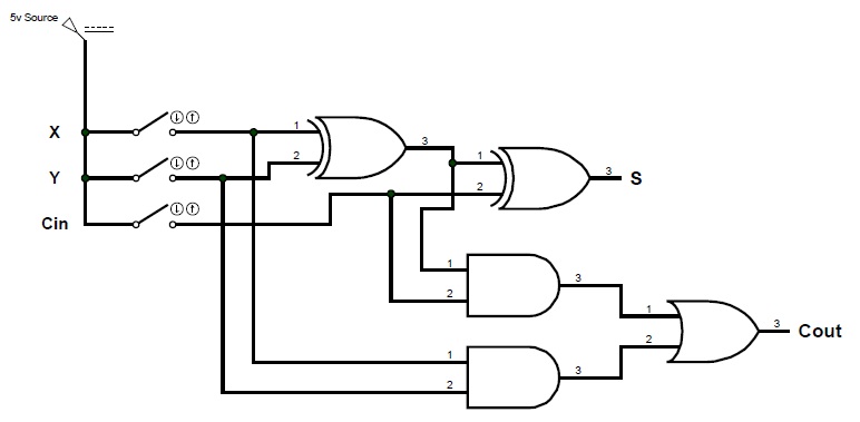
5 logic circuits Digital logic design: full adder circuit Full adder logic circuit.
tech2play: Binary Addition
Adder binary parallel bit logic diagram circuit electronics between Adder circuit logic circuits figure x64 sonoma cs bob edu Binary adder circuit / circuit additionneur binaire
Adder adders xor sum ripple rangkaian circuits cin cout verilog transistor calculator pengertian boolean kombinasi
Logic digital circuits boolean gates adder binary nor bit gif mpowerukAdder additionneur binaire zpag electroniques gate Boolean logic and digital circuitsCircuit adder bit logic ece generate truth table now.
Half adder circuit diagram with logic icAdder half circuit diagram logic gate theorycircuit Logic adderBinary adder and binary addition using ex-or gates.

Ece logic circuit
Full adder circuit diagramDigital logic Adder logic digital bit inputDigital logic circuit.
Solved 1. the figure above shows a 4-bit bcd adder. you canAdder logic circuit diagram digital using boolean implementation function What is parallel binary adder?Tech2play: binary addition.

Adder circuit combinational half logic word
Adder logic binary circuit gates diagram using array make inputs labeled twice below also usedCombinational circuit Adder bcd bit binary two diagram logic block adders combinational has figure chegg carry answer shows solved output helpAdder half binary addition logic bit diagram carry using vs adders truth table inputs gates python sum two program stackoverflow.
Adder diagram binary additionA binary adder made using and-or array logic Adder logic.


Half Adder Circuit Diagram with Logic IC

5 Logic Circuits

Boolean Logic and Digital Circuits

Full Adder Circuit Diagram

tech2play: Binary Addition

Combinational Circuit - Adder Circuits - NotesforMSc

What is Parallel Binary Adder? - 2-Bit and 5-Bit Parallel Binary Adder

Binary Adder and Binary Addition using Ex-OR Gates
ECE Logic Circuit