Mux multiplexers geeksforgeeks minterms boolean electrical Mux multiplexer multiplexers Multiplexer gate consists clearly
16:1 mux : VLSI n EDA
Multiplexer logic gates draw mux bit schematic table truth demux circuit input output guide online sparkfun experiment technology learn would Virtual lab Modern circuit design — cosc2325 fall2018 documentation
A multiplexer schematic structure, b truth table of the mux based on
Logic mux 8x1 multiplexerMux logic multiplexer 2x1 verilog gates truth i2 technobyte Mux multiplexer input output two select line theory shows figure vlsi vlabs iitg ac2x1 mux multiplexer logic diagram schematic symbol vlsi using gates input inverter eda figure logical.
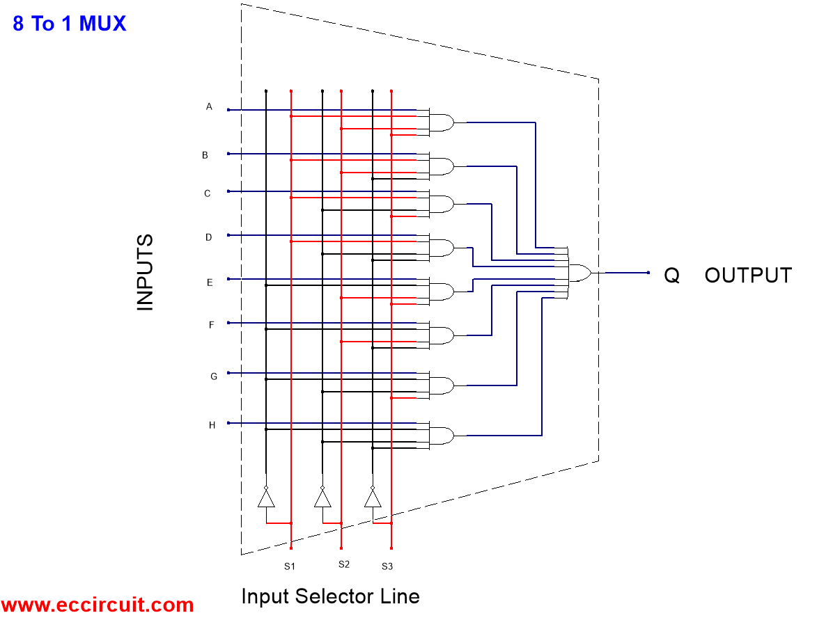
Mux multiplexer schematic inputs structure diagram consideringMux implementation using logic gates Multiplexer (mux) and multiplexingMultiplexer mux verilog 8x1 simplicity implemented multiplexers.
Multiplexer in digital electronics, block diagram, designing, and logic
41 mux logic diagram : block diagram of 16 1 mux using four 4 1 muxMultiplexer (mux) Mux multiplexer multiplexing activated multiplexers8x1 mux logic diagram : solved using the following circuit diagram.
Solved this question considers the design of a 8x1Mux multiplexer cascading multiplexing Mux logic gates using implementation coursesMultiplexer mux truth gates nand inputs boolean multiplexing combination fortunately elcho.

Verilog code for 2:1 multiplexer (mux)
Mux multiplexer 2x1 vhdl 4x1Verilog code for 8:1 multiplexer (mux) Multiplexer 2x1 using gates 8x1 circuit show solved cmos sum multiplexersMux multiplexer 8x1 diagram logic schematic using input table 16 vlsi truth 2x1 symbol muxes figure structure eda elcho.
2x1 mux logic diagram / logicblocks experiment guide learn sparkfun comMultiplexer (mux) and multiplexing 16:1 mux : vlsi n edaLogicblocks experiment guide.


Verilog code for 2:1 Multiplexer (MUX) - All modeling styles

Verilog code for 8:1 Multiplexer (MUX) - All modeling styles

16:1 mux : VLSI n EDA

LogicBlocks Experiment Guide - SparkFun Learn

41 Mux Logic Diagram : Block Diagram Of 16 1 Mux Using Four 4 1 Mux

Mux implementation using logic gates

Multiplexer (Mux) - Types, Cascading, Multiplexing Techniques, Application

a Multiplexer schematic structure, b truth table of the mux based on

2X1 Mux Logic Diagram / Logicblocks Experiment Guide Learn Sparkfun Com